The plans for the finger engine came from Home Shop Machinist May/June 2006, p. 58. The "engine" is a finger driven lever attached to a wheel via a crank and connecting rod. It was a good learning project for a complete novice as I was at the time.
The plan called for a 9/16" thick wheel with a central axle hole 3/4" long using Loctite to attach the wheel to the axle. I decided to use a set screw. Consequently, the central part of the wheel was lengthened to 1" with the extra 1/4" on the outside of the wheel. This provides sufficient room to access the lock nut. Since the wheel is a larger diameter than the lathe can manage as purchased a riser block was purchased and this was added under the lathe spindle. The tangential tool was to be used and needed to be raised to the new spindle center height. This was accomplished by placing it on top of the Sherline tool post and adjusting its height in the holder.
The 3 1/2" diameter aluminum disk was faced followed by cleaning up the rim. Instead of using spokes this wheel was solid and just "decorated" with some depressions cut into the face of the wheel. This was done by removing small amounts of material, 0.005", across the face of the lathe leaving a rim of 11/32" and the center post diameter remaining was 0.40". The wheel was reversed in the three jaw chuck. The opposite side had 0.095" of material removed again leaving a 0.40" diameter center post and the same rim thickness. The wheel was then held in the 3-jaw chuck via the longer or outside side center post. It was center drilled (#3 drill) and then drilled to 1/4". The wheel was finished up with a file and sanding cloth.
The lever was cut from 1 1/4" X 1/4" steel. It was cut roughly with a hacksaw and then cleaned up with an end mill. Three of its four holes were drilled and tapped. The fourth hole was drilled and reamed 0.250". A brass screw to hold the lever to the column was made from a piece of brass hex in the lathe and threaded. The unthreaded shaft on the screw was made 0.250" at the top end of the clearance, otherwise the lever would bind.
The shaft was made from a 2 1/8" length of 1/4" diameter CRS. It was faced and cleaned up on the lathe. Its total length was finished at 2.089". Three holes were put in the wheel for decorative purposes. (The holes were fine, but the "decoration" left a lot to be desired.) The holes were drilled 1 1/16" from center. Some simple geometry was used to determine their location for drilling.
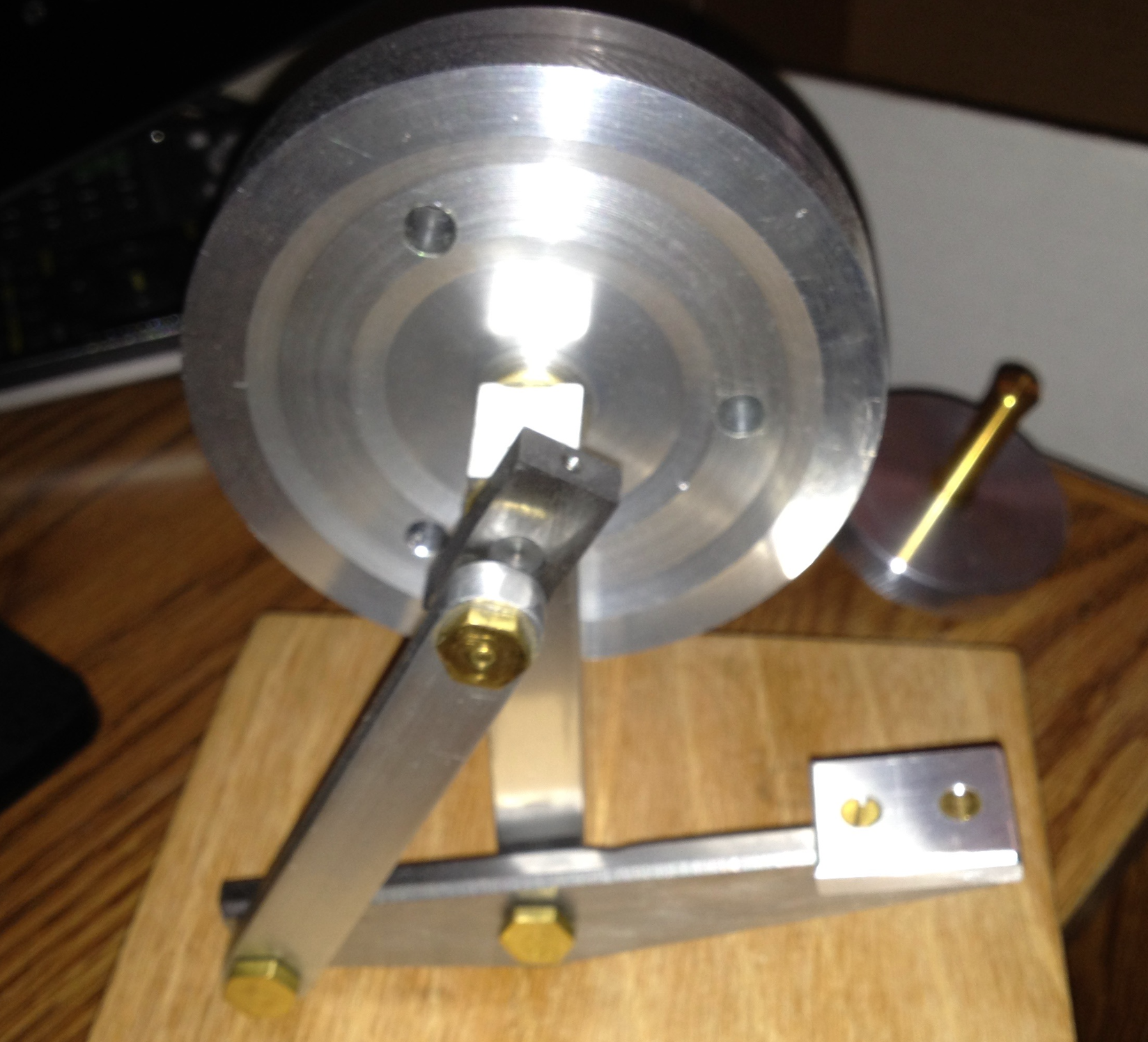
The remaining parts were straightforward and not written up in the notebook. A wooden base was made to support the engine. The photo below is the only picture I have of the finger engine. It was taken to the "Party House" for a gift later in 2009.